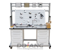
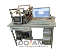
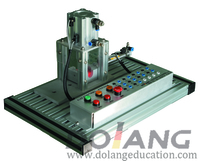
Automotive Electrical Appliance Training Board
Product Quick Detail
- Minimum Order
- 1
- Place Of Origin
- Jinan
- Packaging
- 1 set per wooden
- Delivery
- 15 Days
Specifications
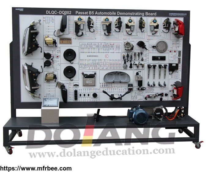
The device is designed based on the electrical equipment system of the finished Volkswagen Passet B5 to holistically demonstrate structures and operation of the meter, lighting, wiper, horn,
ignition, electric window, electric door lock, sound, startup, and charging systems. It applies to the teaching of automobile electric equipment theories and maintenance practicing in secondary and
senior vocational skill schools, normal education and training institutions.
Basic Configuration
The engine control unit, combination instruments, electronic throttle body, left front window motor, right front window motor, left front lock block, right front lock block, left rear window motor,
rear locking block, right rear window motor, right rear locking block , mirror switch, window switch, mirrors, diagnostic seat, crankshaft position sensor, oxygen sensor, air flow meter, knock
sensor, water temperature, intake air pressure sensor, high voltage, ignition coils, spark plugs, fuel injectors ignition switch, comfort system control unit, keys with chip, identification theft
coil, wiper motor, relay and fuse box, generator, starter, battery, sound system, left right rear headlamp assembly, front left and right turn signals, left and right front fog lights, rear left
and right fog lamps, rear left and right turn signals, rear left taillight, license plate lights, interior lights, reading lights, showing wide lights, power switch, training panels, motors, mobile
gantry and casters, supporting manual and training guide book and other components.
Features
1. A real and operable electrical equipment system is used to illustrate the structure of the system.
2. After the electrical equipment system is powered on, switches and buttons of various electric equipment can be operated to demonstrate operation of the meter, lighting, wiper, horn, ignition,
electric window, electric door lock, sound, startup, and charging systems.
3. A color circuit diagram on the instruction board is fixed with aluminum rims. The diagram and electrical equipment system can help trainees learn and analyze the operating principle of the
system.
4.The instruction board is installed with detection terminals to detect electric signals, for example, resistance, voltage, current, and frequency, of circuit components of the electrical
equipment system of the finished automobile.
5.The instruction board is installed with a diagnosis socket connecting a dedicated or universal automobile decoder. The diagnosis socket reads fault codes, clears fault codes, and reads data
stream from the engineer control unit (ECU).
6.The teaching board’s base frame is made of steel and the surface is paint-coated. Self-retention wheels are installed.
7. Fault setting and appraisal system (see fault setting and appraisal Features).
http://www.dolangeducation.com/automotive-training-series/
- Country: China (Mainland)
- Business Type: Dolang technology equipment
- Founded Year: 1998
- Address: No.18-2 Lashan Road, Jinan, Shandong, China
- Contact: Chu Ting
