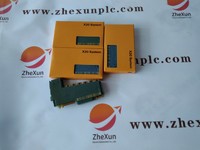
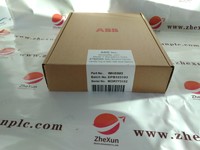
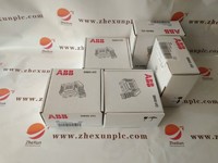
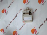
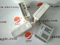
B&r X20CP1584 Central Processing Unit CPU OVP, New
Product Quick Detail
- FOB Price
- USD $999.00 / Piece
- Minimum Order
- 1
- Place Of Origin
- GERMANY
- Packaging
- 1PC
- Delivery
- 15 Days
Specifications
In ladder diagram, the contact symbols represent the state of bits in processor memory, which corresponds to the state of physical inputs to the system. If a discrete input is energized, the memory bit is a 1, and a \"normally open\" contact controlled by that bit will pass a logic \"true\" signal on to the next element of the ladder. Therefore, the contacts in the PLC program that \"read\" or look at the physical switch contacts in this case must be \"opposite\" or open in order to return a TRUE for the closed physical switches. Internal status bits, corresponding to the state of discrete outputs, are also available to the program.
- Country: China (Mainland)
- Business Type: :Bently Nevada, ABB,GE,Rockwell,Foxboro, Invensys Triconex, Westinghouse, Schneider,Siemens,Woodward,GE FANUC,Yaskawa,EPRO,and so on.
- Contact: Holly

