Acrel 300286.SZ AGF-M12T solar power meter combiner box for solar panel PV
Product Quick Detail
- Minimum Order
- 1
- Place Of Origin
- China
- FOB Price
- USD $124.40 / Piece
- Packaging
- Products are packed in carton box with air bubble fim
- Delivery
- 15 Days
Specifications
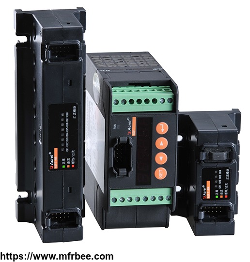
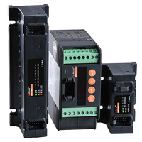
AGF-T Perforation type PV confluenceacquisition device
1 General
AGF-T Perforation type PV confluence acquisition device is specially designed for smart PVcombiner box. It is used for monitoring the running state of solar panels in solar cell arrays, measuringthe currents of solar cell, detecting the state of surge protection devices and DC breaker. The device isequipped with RS485(Modbus) communication port for transmitting all the datas to master device.
2 Product Naming
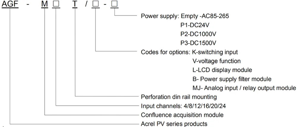
*Power supply filter module is only optional when there is filtering requirements to power supply
3 Characteristics
| 1 | Primary current is connected in through perforation. Easy installation, high safety. |
| 2 | With Hall sensor, the max isolation measuring current 20A |
| 3 | Voltage measurement range for Bus bar is up to DC1kV |
| 4 | LED display, fit for checking and testing operation in wide-temperature or outside environment. |
| 5 | With the function of inner temperature measurement for real-time measurement of the inner temperature of combiner box |
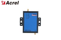
| 6 | With RS485 Modbus RTU |
| 7 | More options of power supply |
| 8 | Compatible with din rail installation and baseboard fixation installation, small dimension saving more box space. |
| 9 | DC Bus bar voltage input circuit with built-in DC 1kV fuse |
4 Product function
Photovoltaic cell open circuit alarm to cooperate with group string voltage and judgeComprehensively
With 3-channel switching state monitoring to collect output idle contact information of DCbreaker,lightning protector.protector etc
Option RS485 port, Modbus-RTU protocol; programmable slave address, baud rate, data format
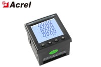
English LCD display,convenient to set parameters and check the data
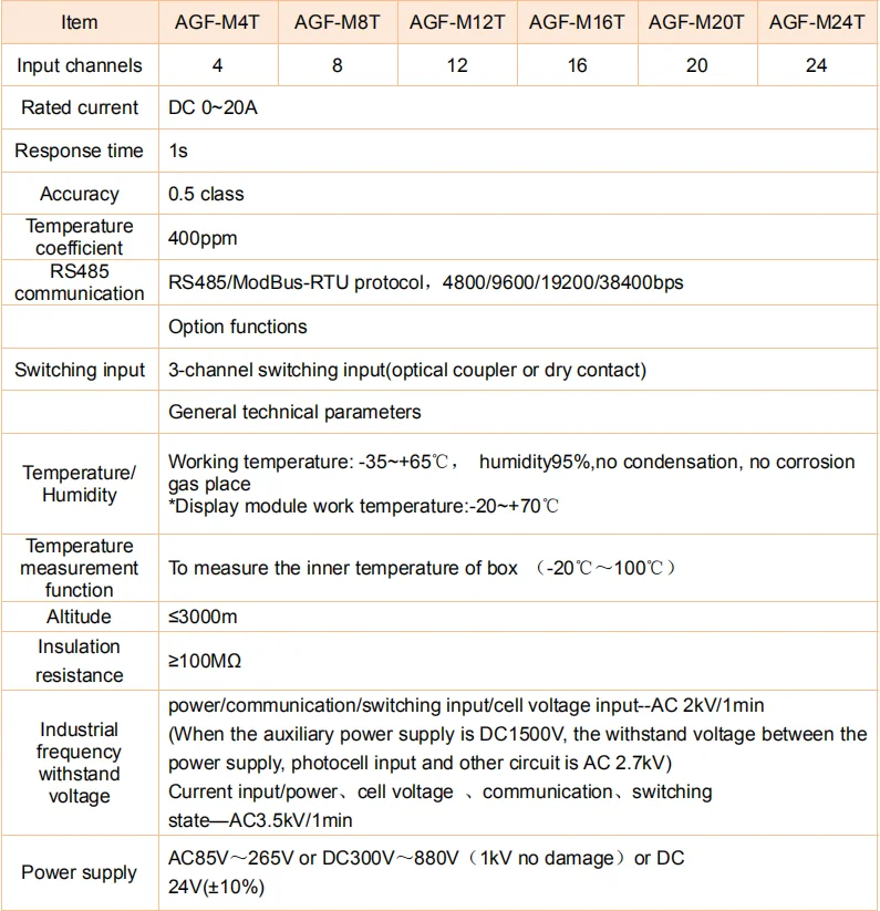
5 Technical Parameters

6 Outline and installation
6.1 Outline dimension
6.1.1 Power supply module and power supply filtering module size(Figure 1)
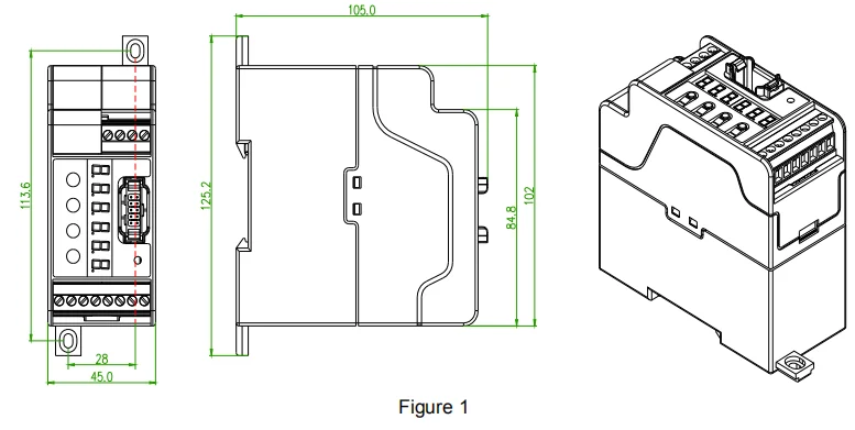
Note: Imaginary line is the fixing size of the bottom plate
As power supply module is heavy, bottom plate is needed in installation to avoid its coming off duringtransportation.
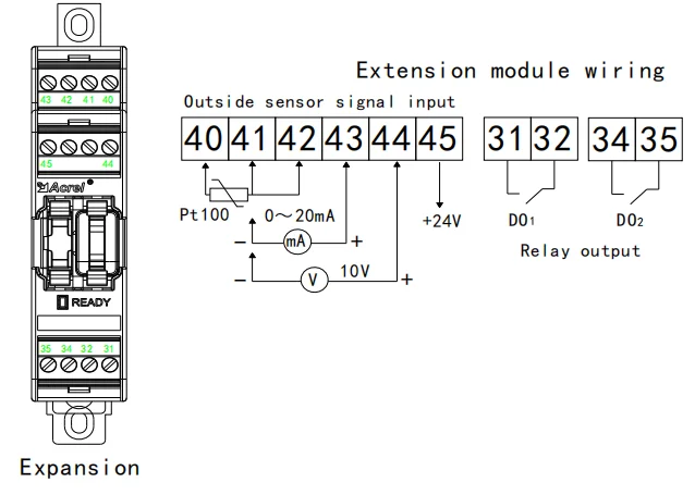
6.1.2 The extension module mounting dimensions (Figure 2)
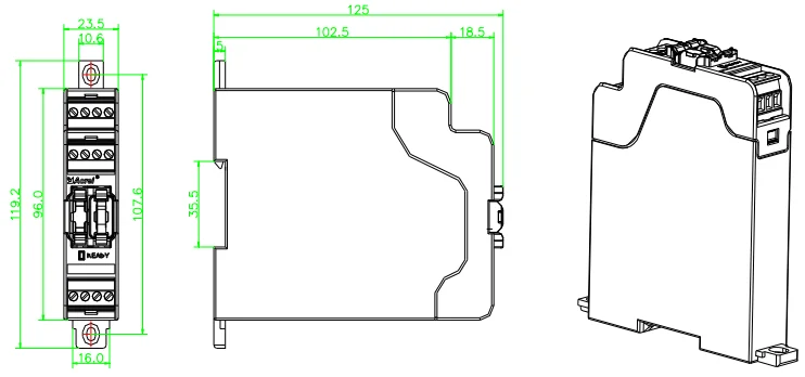
Note: Imaginary line is the fixing size for base plate.
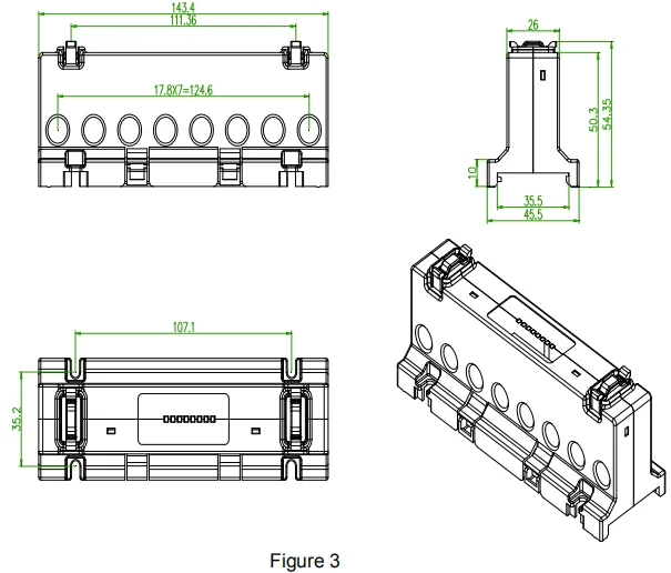
6.1.3 Confluence acquisition module installation dimension
8-channel confluence acquisition module installation dimension(Figure 3)
4-channel confluence acquisition module installation dimension(Figure 4)
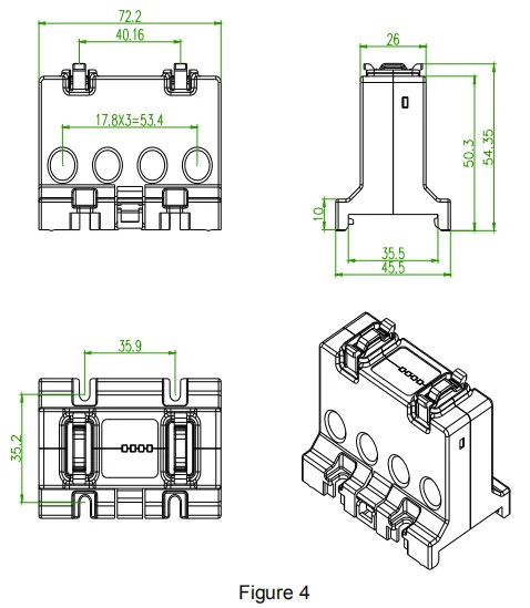
Configuration of 8-channel or 4-channel confluence acquisition module will be decided by actual needs:when 4 channels or less are needed, 4-channel confluence acquisition module will be installed, whenneeded channel number is 5 to 8, 8-channel confluence acquisition module will be installed. When neededchannel number is more than 8, then the number will be divided by 8. If there is a remainder in the resultand the remainder is less than 4, then 4-channel confluence acquisition module will be installed. If theremainder is more than 4, 8-channel confluence acquisition module will be installed.
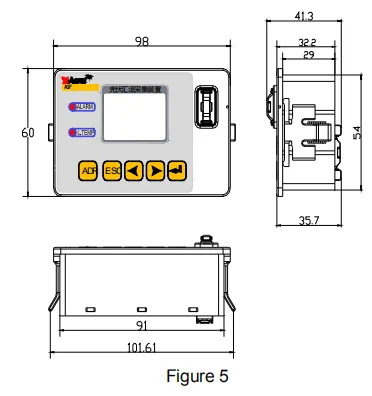
6.1.4 LCD display module installation dimension (Figure 5)
6.2 Connections of modules

6.2.1 Data cable connection way
The connection between each module is through the external data line. Please confirm thesequence of the two external data line ports before connecting each module. Each confluenceacquisition module has two outside connection ports(Figure 4): Port I and Port II, in which Port I is usedto connect upstream module and Port II is used to connect follow-up modules. Please pay attention to itthat the propulsion part of the data line connector must be fixed with the groove on the port.
The connection sequence order of PV confluence acquisition modules must follow: confluenceacquisition module 1's portⅡ-->confluence acquisition module 2's port ,Ⅰconfluence acquisition module 2's portⅡ-->confluence acquisition module 3's port .When connecting the confluence acquisition modules ,multiple confluence modules should be in sequence order, it is not allowed to insert any other function module between two sequenced confluence modules. Wrong connection will lead to abnormal operation of the device.
LCD display module can be connected with Port II of confluence acquisition module, The LCDdisplay module is not necessary to be connected in at ordinary time except when testing and checking.
The address allocation of PV confluence acquisition module is automatically distributed by thepower module(main module), The first confluence acquisition module connected to the power modulewill be distributed automatically with 1st to 8th channels, and the next confluence acquisition moduleconnected to port II will be distributed automatically with 9th to 16th channels, the final confluenceacquisition module is distributed automatically with 17th to 24th channel.
6.2.2 Installation schematic
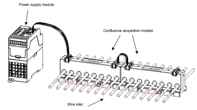
Note: The arrow shows current direction. Wrong connection will lead to abnormal operation of the device.
6.3 Definition of input port
After the address of confluence acquisition module is distributed by the main module,the inputchannel address of first module is from 1st to 8th channel,the input channel address of secondconfluence acquisition module is from 9th to 16th channel,the input channel address of final confluenceacquisition module is from 17th to 24th channel. The input channel definition of 1st to 8th channel of asingle module is shown as Figure 3.
7 Wiring mode
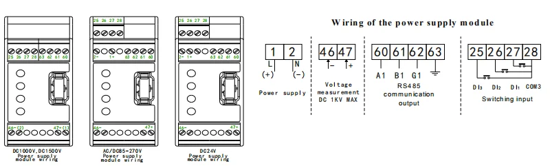
Note: Power supply circuit and voltage measuring circuit must be installed with fuse with 3A rated currentand rated voltage that is the highest working voltage in these circuits to ensure safety.
- Country: China (Mainland)
- Business Type: sensor,meter, solustions
- Market:美洲
- Founded Year:2004
- Address:No.5 Dongmeng Road, Nanzha Street,Jiangyin City,Jiangsu Province,China.
- Contact:Sandra Mo