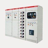
KYN28A-12 Armored Central AC Metal-enclosed Switchgear
Specifications
KYN28A-12 Armored Central AC Metal-enclosed Switchgear
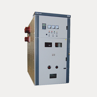
KYN28A-12 armored central AC metal-enclosed switchgear (hereinafter referred to as switchgear) is a new product designed and developed by Baixing based on the absorption of advanced manufacturing technology at home and abroad. It can replace all kinds of old metal-enclosed switchgear. Such as KYN1-12, JYN2- -12 and other products.
Its products have the following distinct advantages:
1.1 The outer shell of the product is completely assembled from aluminum-zinc-copper plate by CNC machine tool and formed by bolts. It has high mechanical strength, effectively guarantees the neatness and beauty of the product, and the door is spray-coated. It has strong impact resistance and corrosion resistance. The product enclosure has an IP4X rating. (Can be changed to iron plate according to customer needs).
1.2 The main switch of this product can be equipped with VB4 vacuum circuit breaker produced by ABB Company, C3 series fixed load switch, and also can be equipped with a variety of domestic series vacuum circuit breakers (such as VS1, VHI, VK, ZN 28) to replace Similar products abroad.
1.3 Regardless of which circuit breaker is selected, the bare conductor air insulation distance can be guaranteed to be greater than 125mm, and the composite insulation is greater than 60mm. The circuit breakers have the unique advantages of long life, high parameters, low maintenance and small size.
KYN28A- 12 armored centrally-mounted metal-enclosed switchgear is suitable for 3.6--12KV three-phase AC 50Hz power grid, as a means of receiving and distributing electrical energy, and controlling, monitoring and protecting the circuit. Can be used for single busbars, single busbar segmentation systems or dual busbar systems. The switchgear complies with IEC298 "AC metal-enclosed switchgear and control equipment with rated voltage above 1 KV and below 52KV", IEC694 "Common Terms of High-Voltage Switch and Control Equipment", China GB3906 "3--36KV AC Metal-Enclosed Switchgear" and DIA04 "Order AC high voltage switchgear ordering conditions", Germany DIN.VDE0670 "AC switchgear with rated voltage above 1 KV" and other standards. And has a complete and reliable anti-misoperation function.
Model and its meaning
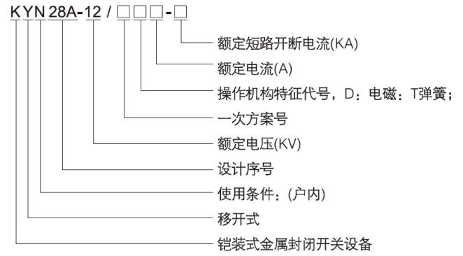
Normal use condition
2.1 ambient air temperature: . upper limit +40 ° C, lower limit - 10 ° C;
2.2 Relative humidity: the daily average is not more than 95%, and the monthly average is not more than 90%;
2.3 Altitude: no more than 1000m;
2.4 The seismic intensity does not exceed 8 degrees;
2.5 No fire, explosion hazard, serious pollution, chemical corrosion and severe vibration.
When the conditions of use exceed the above range, the user should negotiate with our company to determine the allowable range and technical measures.
Note:
1 The electric heater should be turned on when the relative humidity is greater than 70%.
2 Where the altitude is more than 1000m, it shall be treated according to JB/Z102-71.
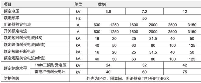
The main technical parameters
Switching equipment technical parameters
VD4, VS1-12 vacuum circuit breaker technical parameters
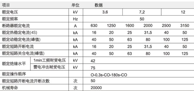
Operating mechanism technical parameters

Mechanical characteristics of VD4 and VS1-12 vacuum circuit breakers
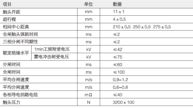
When the circuit breaker is used to control a 3 - 10kV motor, if the starting current is less than 600A, a metal zinc oxide arrester must be added. The specific requirements are negotiated by the user and our company; when the circuit breaker is used to open the capacitor bank, the rated current of the capacitor bank is not It should be greater than 80% of the rated current of the circuit breaker.
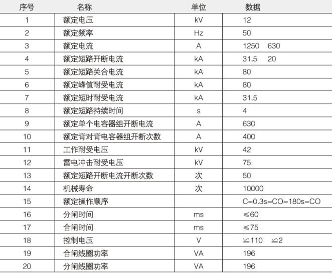
Main technical parameters of ZN port-12 (VH1) vacuum circuit breaker
Use and description
1. In the operation of the switchgear, in addition to the relevant regulations, the operator should also pay attention to the following problems:
1. 1 operating procedure
Although the switchgear is designed to ensure the correct interlocking of the operating procedures of the various parts of the switchgear, the push and exit of the various parts of the switchgear by the operator should be carried out strictly in accordance with the operating procedures and the requirements of this technical document, and should not be operated at will. It should not be forced to operate without analysis when the operation is blocked. Otherwise, it may cause equipment damage or even cause an accident.
1 1.1 Operation of circuit breaker cabinet without grounding switch
a. Insert the circuit breaker removable parts into the cabinet: Before the circuit breaker trolley is ready to be pushed into the cabinet from outside the cabinet, carefully check whether the circuit breaker is in good condition, whether there are missing parts, whether there are tools and other debris placed on the mechanism. Inside the box or switch, after confirming that there is no problem, mount the cart on the rotating car and lock it. Push the transfer vehicle to the front of the cabinet, raise the trolley to a suitable position, insert the front positioning lock plate of the transfer vehicle into the partition socket in the cabinet and lock the transfer vehicle and the cabinet, then open the locking hook of the circuit breaker trolley and drive the trolley It is pushed into the cabinet and locked at the same time. After confirming that the car has been locked with the cabinet, unlock the transfer vehicle and the cabinet and push the transfer vehicle away.
b. The car is operated in the cabinet: after the car is loaded into the cabinet from the transshipment, it is in the disconnected position in the cabinet. If the car is to be put into operation, firstly, the car is in the test position, and the auxiliary circuit plug should be plugged in. Then the test position indicator on the panel of the instrument room is on. At this time, the electric operation test of the trolley can be carried out when the main circuit is not connected. If you want to continue the operation, you must first close all the doors and insert the key into the lock hole. , lock the door and confirm that the circuit breaker is in the open state (see d). At this point, the handle operation handle can be inserted into the operation hole on the middle panel, and the handle will be turned clockwise until the handle is obviously blocked and the clear auxiliary switch is switched, and the working position indicator on the instrument panel panel is bright, then Remove the shaker. At this time, the main circuit is turned on, and the circuit breaker is in the working position, and can be combined and divided by the control circuit. If you are ready to withdraw the trolley from the working position, first of all, you should confirm that the circuit breaker is in the open state (see d), insert the handcart to operate the crank, turn counterclockwise until the rocker is blocked and hear the clear auxiliary switch switching sound, the car Then return to the test position. At this point, the main circuit has been completely disconnected and the metal shutter is closed.
C. Take out the trolley from the cabinet: Right to take out the trolley from the cabinet, first make sure that the trolley is in the test position, then touch the auxiliary loop to catch the head and lock the tap on the frame. At this time, push the transporter to the front of the cabinet. (The same time as loading the car into the cabinet), then unlock the handcart and pull it out. When the handcart completely enters the transfer vehicle and confirms that the transfer vehicle is locked, the lock of the transfer vehicle and the cabinet is released, and the transfer vehicle is pulled backwards by an appropriate distance, and then gently lowered and stopped. If the car is to be transported by a transfer vehicle for a long distance, care must be taken in the process of pushing the car to avoid accidents during transportation.
d. Confirmation of the opening and closing status of the circuit breaker in the cabinet: The opening and closing state of the circuit breaker can be determined by the two sides of the circuit breaker's hand truck panel, the closing indicator and the instrument panel panel. If the green opening indicator on the handcart panel is seen through the glass window of the middle panel of the cabinet, it is determined that the circuit breaker is in the open state. At this time, if the auxiliary circuit plug is electrically connected, the closing indicator light on the instrument room panel is illuminated. .
1.1.2 Operation of the circuit breaker cabinet with earthing switch The procedure for pushing the circuit breaker hand truck into the cabinet and exiting the hand truck from the cabinet is exactly the same as that of the circuit breaker without the earthing switch. Only when the handcart is in the cabinet and during operation
Pay attention to the following during the switching process:
a hand cabinet operation
When preparing to push the handcart into the working position, in addition to complying with the requirements of b in 1.1.1, it should also be confirmed whether the grounding switch is in the open state, otherwise the next operation cannot be completed.
b. Combined and divided grounding switch operation
To make the grounding switch, first make sure that the handcart has been retracted to the test, 8 off position, and remove the pusher handle, then press the interlocking plate at the grounding switch operating hole, insert the grounding switch operating handle, turn clockwise At 90 degrees, the grounding switch is in the closed state. If you turn 90 degrees counterclockwise, the grounding switch will be opened.
1.1.3 General isolation cabinet operation
The isolated handcart does not have the ability to press and disconnect the load current, so it is not allowed to pull the handcart under load. When operating in an isolated hand truck cabinet, it must be ensured that the circuit breaker that matches it is first opened (see 1 1 1 d), and the auxiliary contact switch is released and the handrail is isolated on the handrail after the circuit breaker is opened. The electrical interlock is the only way to operate the isolated car. The specific operating procedures are the same as those for operating the circuit breaker.
1.2 Notes on using interlocks
1.2.1 The interlocking function of this product is mainly based on mechanical interlocking, supplemented by electrical interlock to realize its function. It can realize the requirement of “five-proof” blocking of the switch, but the operator should not neglect the operation. The requirements of the regulations, only the combination of the rules system and technical means can effectively play the role of the interlocking device to prevent accidents.
1.2.2 The input and release of the interlock function of this product are mostly realized during normal operation. Do not add additional operations.
step. If the operation is found to be obstructed (such as increased operational resistance), first check whether there is a possibility of misoperation, and not force the operation to damage the equipment, or even lead to accidents.
1.2.3 This interlock allows emergency unlocking due to special needs (such as the interlock of the lower panel of the cabinet and the grounding switch). The use of emergency unlocking must be prudent, should not be used frequently, and take necessary protective measures when using it. - Immediately after processing, the interlocking state should be restored.
2. The maintenance of the switchgear should be carried out in accordance with the relevant regulations. Users are advised to pay special attention to the following points:
2.1 Check the condition of the circuit breaker according to the requirements of the installation and operation manual of the vacuum circuit breaker, and make necessary adjustments.
2.2 Check the condition of the handcart propulsion mechanism and its interlock, and deal with it in time.
2.3 Check the condition of the main circuit, wipe out the old grease on the static and dynamic contacts, check whether the spring force has obvious change, whether there is abnormal oxidation of the coating due to excessive temperature, if any of the above, it should be treated in time.
2 4 Check the auxiliary circuit contacts for any abnormalities and perform necessary trimming.
2.5 Check the condition of each part of the grounding circuit, such as the grounding contact, the main grounding wire and the grounding wire of the door to ensure its continuity of conduction.
2.6 Check the fasteners of each part. If it is loose, it should be tightened in time.
- Country: China (Mainland)
- Contact: Qing zhu


